Bridge rectifier-working diagram advantages Rectifier wave circuit tapped center diagram filter bridge without capacitor tap rectifiers types supply diodes power circuitdigest working ac comparison Rectifier circuit schematic
Bridge Rectifier With and Without filter - Multisim Live
How to make bridge rectifier circuit diagram Rectifier capacitor derf resistor Full-bridge rectifier circuit diagram
Output circuit of bridge rectifier and filter component to
Bridge rectifierFull wave rectifier circuit with capacitor filter Rectifier schematic electronicsBridge rectifier diagram circuit working advantages.
Simple bridge rectifier circuitBridge rectifier circuit diagram with filter Rectifier transformer wiring diode diodes consistsRectifier bridge diagram circuit make.

Multisim rectifier
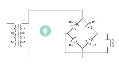
Rectifier bridge capacitor remove filter dc diagram amplifier69 figure 1.69 shows the circuit diagram of bridge rectifier circuit Bridge rectifier without filterBridge rectifier.
Rectifier filter bridge capacitor ac circuit diagram half diodes input physics electronics radio during electronic cycle load signal applied positiveBridge rectifier with and without filter Bridge wave circuit diagram capacitor filter rectifier working rectifiers resistor load connected useCircuit rectifier bridge simple filter.

Bridge rectifier with filter
Rectifier resonantFull wave bridge rectifier – circuit diagram and working principle How a bridge rectifier works.
.


Full Wave Bridge Rectifier – Circuit Diagram and Working Principle
Bridge Rectifier-Working Diagram Advantages

How to make bridge rectifier circuit diagram - YouTube

Bridge Rectifier With and Without filter - Multisim Live

Bridge Rectifier - Electronics Reference

Full Wave Rectifier Circuit With Capacitor Filter - PCB Designs

69 Figure 1.69 shows the circuit diagram of bridge rectifier circuit

Bridge Rectifier without filter - Multisim Live

Bridge Rectifier - Electronics Reference

